In EV battery safety, one failed cell is only the start. The real danger is a chain reaction that keeps spreading.
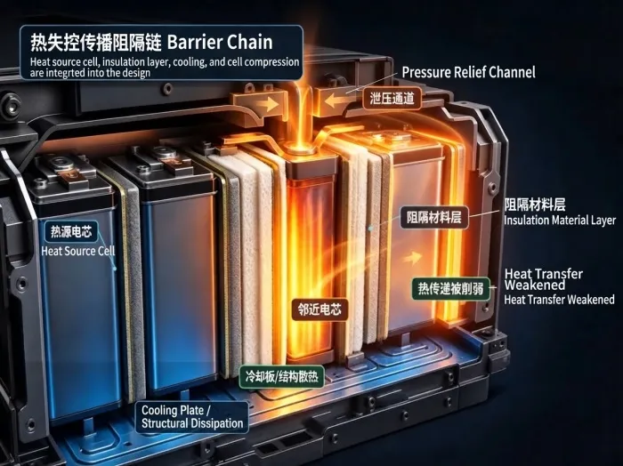
When an internal short circuit or thermal runaway makes a cell release intense heat and vent, that heat spreads fast through cell casings, tabs, busbars, module frames and baseplates, as well as jets of hot gas. Keep heating the cells next door to their critical temperature, and they can fail one after another. That is thermal runaway propagation.
The goal of a thermal barrier is not simply to survive the highest possible temperature. It is to interrupt heat transfer between cells, contain the initial failure and stop it spreading.
What it blocks: heat flux, thermal radiation, flames, hot gas and conductive heat paths. What it accomplishes: crucial time for alarms, power reduction, high-voltage isolation, pressure relief, firefighting and evacuation.
You will often hear these materials described as a firewall between cells. It is misleading.
Space inside a battery pack is tight. Barriers cannot keep getting thicker or heavier. They also have to handle vibration, compression, thermal cycling, moisture, particle shedding, assembly tolerances, cooling arrangements, disassembly and ageing. A practical barrier balances safety, weight, volume, cost and consistent manufacturing.
Good insulation alone does not make a material right for an EV battery pack.
Adding it can reduce cell spacing, change module clamping forces and alter cooling paths. Over time, vibration can make it shed particles, deform or lose contact. Battery safety ultimately depends on how the whole pack handles real thermal runaway conditions.
Before comparing material names, map how heat can spread. There are 4 typical routes:
Heat-transfer route | How it works and what engineers face |
Conduction through cell casings | Cell gaps are tiny. Prismatic, blade and pouch cells make contact differently, so barrier placement and compression vary too. |
Conduction through tabs and busbars | Electrical connections need high conductivity, but their metal also carries heat quickly through tabs, busbars and bolts. |
Jets of hot gas and particles | Venting releases hot gas, combustible components and particles with high melting points. Thermal conductivity alone misses the impact of jet erosion and ablation. |
Heat transfer through cold plates and structures | Cold plates normally remove heat, but during a failure they can redistribute it. Insulation needs to work with bottom cooling and top-cover venting. |
Reliable designs often combine thin layers: insulation to cut heat flow, a fire-resistant layer to resist jet erosion, electrical insulation for high voltage, and structural parts for retention and directed venting.
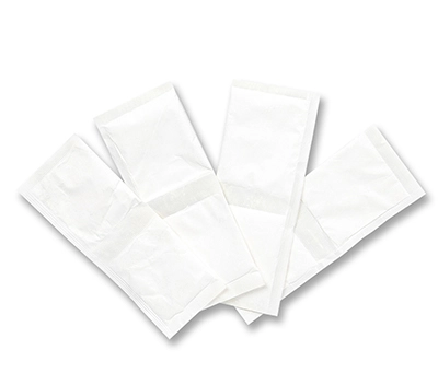
Strengths: low thermal conductivity and density at room temperature, making it useful for steady-state insulation in tight spaces.
Limitations in real assemblies:
Particle shedding and declining performance: cutting, assembly and vehicle vibration can release nanoscale dust. Damage to the pore structure can raise thermal conductivity from around 0.018 W/(m·K) to above 0.025, while the dust can contaminate electrical components inside the pack.
Compression damage: module clamping reduces thickness and changes contact thermal resistance. Repeated thermal cycling and vibration can cause permanent deformation, poor contact and loss of elastic recovery.
Moisture and ablation limits: poorly water-repellent products can absorb moisture over time, sharply increasing thermal conductivity. Hot gas jets can also burn through an unprotected aerogel layer.
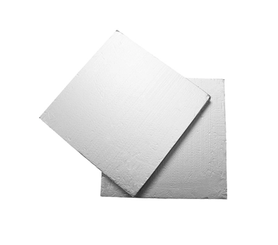
Strengths: excellent resistance to very high temperatures, flame and electrical breakdown. Often used to isolate modules and high-voltage areas.
Limitations: brittle, with little cushioning. Fit and impact protection need careful design.
Strengths: absorb heat through latent heat or expand at high temperatures to form a char layer that blocks heat flow.
Limitations: latent-heat buffering runs out once the material has fully changed phase. Flammability, leakage and expansion ratio need tight control.
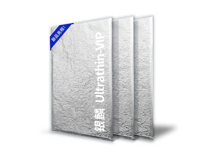
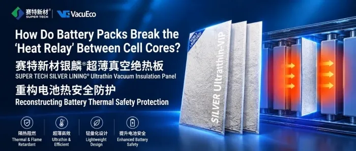
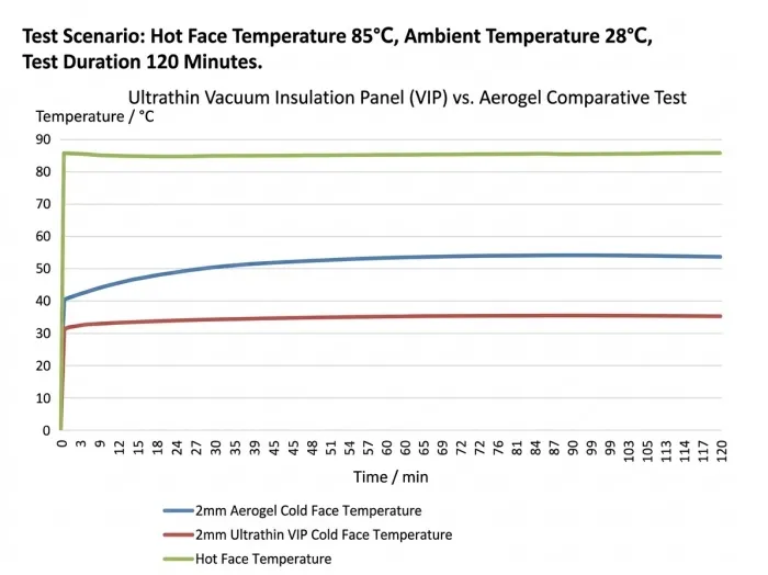
To tackle particle shedding, performance loss under compression, bulky insulation and thermal-runaway jets, Super Tech Advanced Material, offers a new composite solution: ultra-thin vacuum insulation panels.
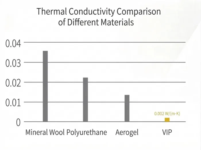
Thermal conductivity goes as low as 0.002 W/(m·K), with 8–10 times the thermal resistance of conventional materials. Even in narrow cell gaps, a barrier can deliver effective insulation at 1/3 the thickness of conventional materials—or less.
A dense, preformed composite-film enclosure prevents particle shedding and moisture uptake. Puncture resistance is more than 6.2 times that of conventional VIP, with an overall leak rate below 3×10⁻⁶ Pa·m³/s. It is designed to last as long as the battery pack without maintenance.
The panels insulate while absorbing the stresses caused by cell expansion during charging and discharging. They also withstand 3800 VDC and provide high electrical insulation. Room-temperature thermal conductivity remains at just 3.0 mW/(m·K) after 1000 h at 85℃/85% RH and after copper-acetic salt-spray testing.
Property | Specification |
Thickness | 1–5 mm |
Initial thermal conductivity at room temperature | As low as 2.0 mW/(m·K) |
Relative thermal resistance | 8–10 times that of conventional insulation |
Puncture resistance | ≥ 6.2 times that of conventional VIP |
Heat-seal strength | 40% higher than conventional designs |
Temperature range | -40 ℃ to 90 ℃ |
Panel design | Ultra-thin, with no folded edges and a preformed barrier-film shell. Flexible, bendable options fit curved surfaces and complex structures. |
Service-life approach | Maintenance-free for the life of the battery pack |
Certifications | REACH, RoHS; Supply-chain quality system: IATF 16949 |
Customisation | Custom dimensions, shapes, thicknesses and thermal conductivity |
Room-temperature performance after 1000 h at 85℃/85% RH | As low as 3.0 mW/(m·K) |
Thickness and dimensions | Thickness: 1–5 mm Dimensions: 100×100 to 600×1000 mm |
Thermal conductivity after 240 h of copper-acetic salt-spray testing | As low as 3.0 mW/(m·K) |
Voltage withstand | 3800 VDC, leakage current <1 mA |
Electrical insulation | ≥500 MΩ at 1000 V |
Density range | 400–550 kg/m3 |
Thermal conductivity usually gets top billing. It matters, but thermal runaway is nothing like a steady-state insulated-box test. Temperatures rise sharply in a very short time, with jet erosion and deformation happening too. Assess performance across 5 dimensions:
Does the material hold its shape at high temperatures? Does it crack, shed particles or develop holes?
How do thickness, porosity and contact thermal resistance change under clamping?
After runaway starts, can it maintain high-voltage insulation despite heat, carbonised residue and electrolyte splashes?
Do ablation products add smoke or corrode nearby metal and electronics?
Can it be die-cut and placed automatically? Do the edges shed particles? Does prolonged vibration or moisture exposure degrade performance?
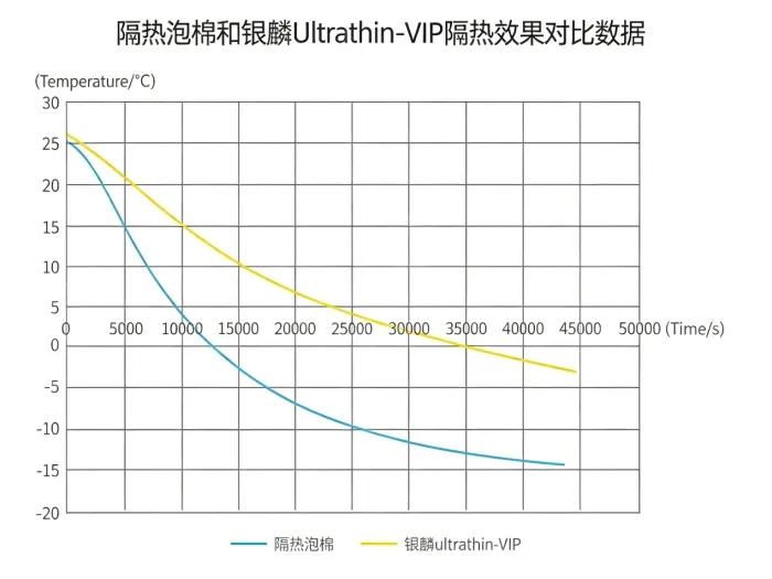
Test results: at -20 ℃, a battery pack fully lined with 3 mm vacuum insulation panels from Super Tech Advanced Material took 10 hours to cool to 0 ℃, compared with 3.5 hours for conventional foam—nearly 3 times as long. That demonstrates high steady-state thermal resistance and helps improve EV driving range in winter.
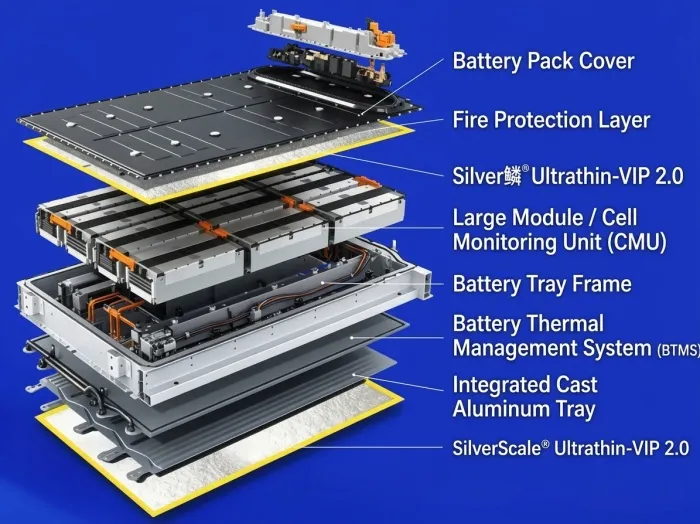
In normal operation, heat needs to escape easily. During thermal runaway, it needs to stay away from neighbouring cells. Those goals pull in opposite directions.
More or less? Too much barrier material hurts everyday cooling. Too little may not provide enough protection during runaway.
Soft or stiff? Too soft creates assembly and support problems. Too stiff makes cell expansion and clamping forces harder to manage.
Good battery safety design does not turn the pack into a thermos. It sends heat along the intended cooling paths in normal use, then blocks the most dangerous routes during a failure.
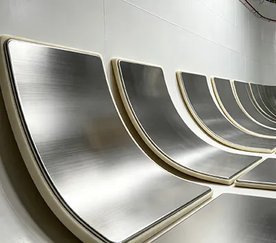
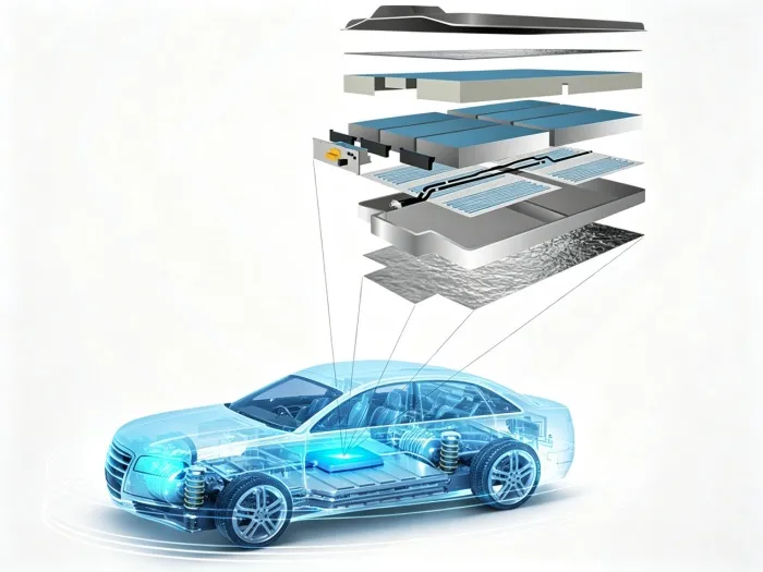
For example, 1.5 mm ultra-thin VIP can be fitted between cells, under the pack’s top cover or at key points on a water-cooling plate. Their slim profile leaves more room for cooling, while thermal conductivity of just 0.002 W/(m·K), or 2.0 mW/(m·K), limits unwanted heat flow. That helps reconcile cooling with thermal isolation.
Next time you see a thermal-runaway barrier claim or solution proposal, ask these 6 questions:
1. What was tested? A single material sample, or thermal propagation across a complete module or pack?
2. What triggered it? A heater, nail penetration, overcharging, or an actual cell entering thermal runaway?
3. What counts as success? A lower temperature at one point, a longer delay, or no runaway in neighbouring cells?
4. What happens after assembly? How much thickness remains under module compression? Does long-term vibration cause particle shedding, breakdown or loss of contact?
5. What else was checked? Fire resistance, electrical insulation, smoke, particle shedding, moisture uptake, vibration and ageing?
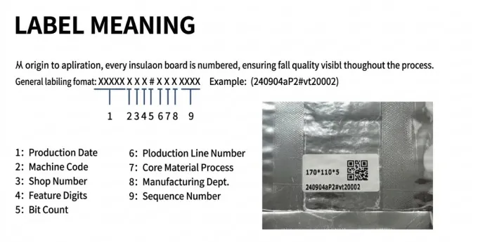
6. Can the supplier deliver consistently? Is its quality system certified to IATF 16949, with production capacity to match? Super Tech Advanced Material’s annual capacity of nearly 11 million m² and its Hefei facility support reliable delivery and consistent quality.
“Withstands 1000 °C” is not enough to judge a thermal-runaway barrier.
The real test comes after one cell fails. Do its neighbours absorb less heat, reach dangerous temperatures later, or avoid the chain reaction altogether? Battery safety depends on giving the system time to respond. Super Tech Advanced Material’s ultra-thin vacuum insulation panels aim to secure that time with stable insulation, no particle shedding, high puncture resistance and a service life matched to the pack—all in a design built for volume production.
 English
 日本語
日本語 한국어
한국어 français
 Deutsch
 Español
 italiano
 русский
 português
 العربية
 Türkçe