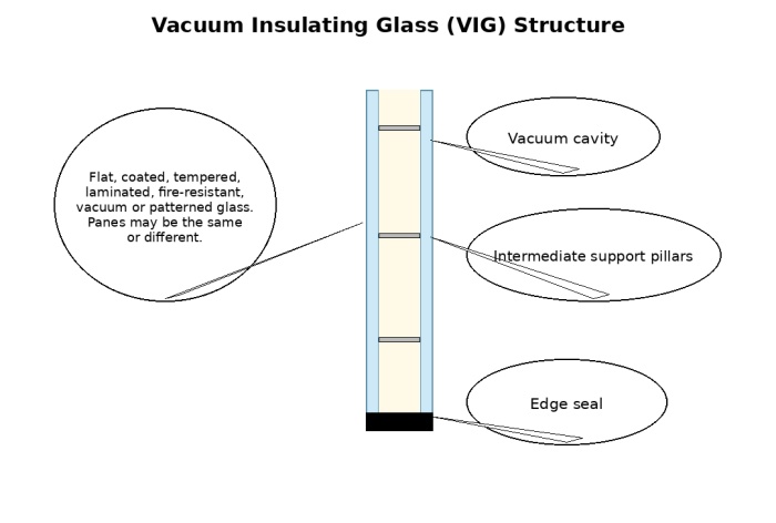
A vacuum insulating glass system consists of two or more panes separated by support pillars to form a vacuum cavity between the panes. The structure is shown below:
Spectral-optical performance: transmission, reflection, absorption, shading, visible light and total solar transmittance. Model boundary: solar radiation only, with outdoor and indoor reflectance assumed to be zero.
Thermal performance: residual-gas heat transfer, radiative heat transfer and solid heat transfer. Boundary condition: no solar radiation in the thermal calculation.
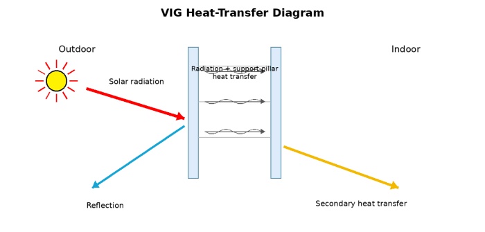
VIG and IGU systems both use transparent glass as the main component. However, the different gas conditions in their cavities create both similarities and differences in heat-transfer behaviour.
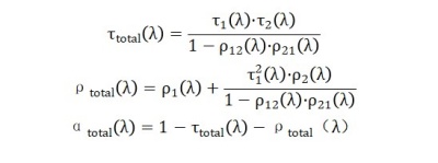
Because both systems use the same transparent glass, their visible light transmittance and direct solar transmittance are essentially the same. The only slight difference is the minor obstruction from the micro-support points, below 0.5%; this is ignored for simplicity, and direct solar-spectrum transmittance is treated as identical. Both systems use an iterative method to calculate direct solar transmittance.
In a VIG cavity, gas molecules move independently. In theory, two gas molecules never collide and there is no mutual heat exchange between molecules. Heat transfer between the panes is limited to residual-gas conduction and conduction through the support pillars.
The formula for total solar transmittance remains valid, but heat absorbed by the outer pane can transfer only a small amount to the inner pane by radiation. This sharply reduces secondary heat transfer and lowers total solar transmittance.
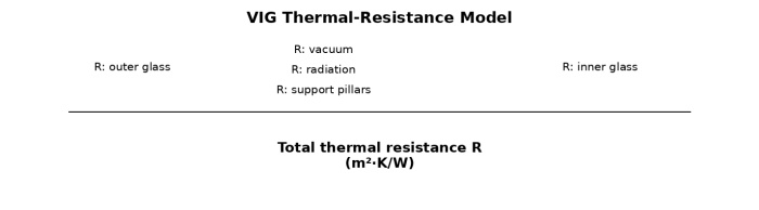
The VIG cavity pressure must reach 5×10⁻²Pa. At this pressure, the gas heat-transfer coefficient is about 0.04W/㎡·K, which is negligible in engineering calculations.
Total solar transmittance through VIG consists of direct transmittance plus secondary heat transfer. Secondary heat transfer is governed by radiative heat transfer and heat transfer through the support pillars:

For VIG: Rgap: cavity thermal resistance; Rso=1/23=0.04㎡·K/W; Rio=1/8=0.125㎡·K/W
hgap: cavity thermal conductance, determined by three parallel paths: residual-gas conductance hg, inter-pane radiative conductance hr and support-pillar thermal-bridge conductance hz. Under high vacuum, residual-gas conductance hg=0.
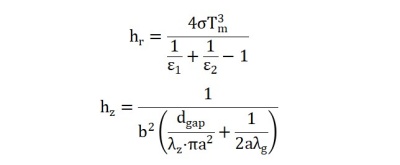
λz: support-pillar thermal conductivity, 16W/m·K for stainless steel; λg: glass thermal conductivity, 1W/m·K; b: support spacing, set to 0.04m; a: support radius, set to 0.00015m; dgap: support height, or cavity thickness, set to 0.0005m.
Glass parameters used in the calculation are shown below. All glass is from CSG.
Glass | Solar parameters (Solar) | Visible light (Visible) | Emissivity (ε) | Notes | |||||||
Tsol1 | Tsol2 | Rsol1 | Rsol2 | Tvis1 | Tvis2 | Rvis1 | Rvis2 | ε1 | ε2 | ||
LB69-6 | 0.345 | 0.345 | 0.392 | 0.424 | 0.679 | 0.679 | 0.099 | 0.060 | 0.84 | 0.033 | Double-silver |
Clear glass | 0.822 | 0.822 | 0.074 | 0.074 | 0.897 | 0.897 | 0.081 | 0.081 | 0.84 | 0.84 | |
Substituting the values gives:
Tvis=0.61; Tsol==0.293; Asol=0.306; hr=0.187 W/m2·K; hz=0.166 W/m2·K; hgap=0.353 W/m2·K; Rgap=2.83m2·K/W; Fi=0.01336; qi=0.01336*0.306=0.0041; g (SHGC)=0.293+0.0041=0.297; SC=0.297/0.87=0.34.
Adding the thermal resistance of the two glass panes to the cavity resistance gives the total VIG system resistance and therefore K(U). With each pane 6mm, or 0.006m, Rtotal=2·d/λg+Rgap=0.012+2.83=2.95m2·K/W, giving K(U)=0.32W/㎡·K.
The effect of glass composition is the same as for an IGU and is not repeated here. However, the factors governing secondary heat transfer within total solar transmittance are different and are discussed below.
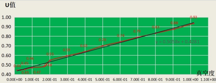
The U-value in the chart varies by about 10% around the 10^-1 vacuum range. This reflects the change in molecular gas conduction as the cavity moves from rough vacuum to high vacuum. Once high vacuum is reached, VIG K(U) becomes essentially stable. To fully use vacuum insulation, the system must operate well within the molecular mean-free-path regime.
The measured data show that stable VIG performance requires a vacuum pressure of 5×10⁻²Pa. Pursuing a substantially higher vacuum sharply increases process cost, while failing to meet this value prevents the VIG system from fully delivering vacuum-insulation performance.
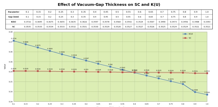
The chart varies vacuum-gap thickness while holding all other structural parameters constant, showing its effect on SC and K(U).
Under high vacuum, gas conduction is negligible. The small changes shown are therefore caused by changes in support-pillar height. SC is effectively unaffected, while K(U) changes slightly: every 0.05mm increase in thickness lowers K(U) by about 0.5% in a linear relationship.
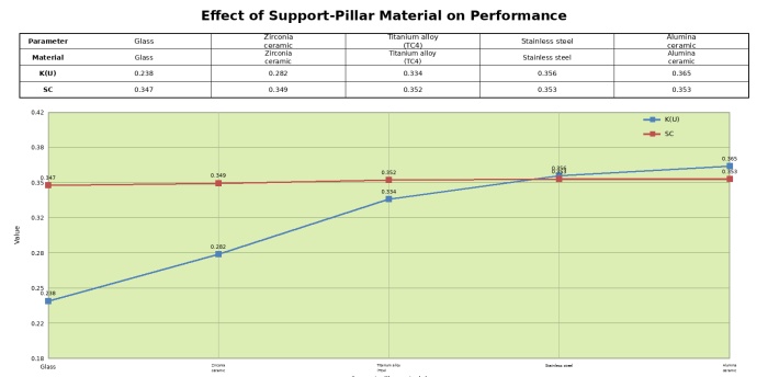
Material | Thermal conductivity |
Glass | 1 |
Zirconia ceramic | 2.2 |
Titanium alloy (TC4) | 6.8 |
Stainless steel | 16 |
Alumina ceramic | 30 |
As support-pillar thermal conductivity increases, the VIG SC rises slightly, but the change is minimal.
K(U) changes significantly. Compared with stainless steel, glass lowers K(U) by 33%, zirconia ceramic by 20% and titanium alloy TC4 by 6%, while alumina ceramic raises it by 2.5%.
Glass is brittle, while zirconia and alumina ceramics are hard and brittle. In use, the supports may be crushed or may damage, crack or break the structural glass, so closer support spacing is required. Titanium alloy and stainless steel are tough and cause less structural damage in testing, allowing wider spacing and therefore better appearance and optimised performance.
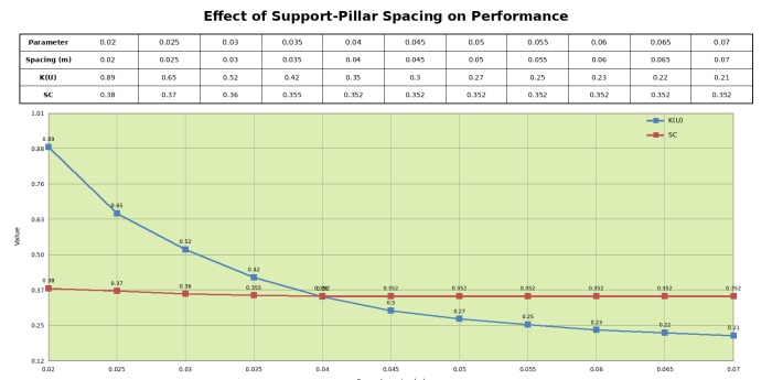
As support spacing increases, SC decreases slightly, but the overall change is so small that it can be treated as negligible.
K(U) decreases markedly along a curve as support spacing increases. However, the supports must keep the panes apart, so spacing must balance the physical properties of the support material and the structural glass. Brittle, rigid supports such as glass and ceramics cannot be spaced too widely. Tough supports must also account for glass deflection, prevent the panes from touching and avoid edge microcracks that reduce glass strength.
With tough supports, typical spacing is about 25-60mm for glass thicknesses of 3-8mm. Thicker glass permits wider spacing. This is why the same coating system can produce a lower K(U) when used on thicker glass.
The above analysis identifies the factors affecting VIG thermal performance apart from the glass itself.
The primary factor is cavity gas pressure. Stable VIG operation depends on maintaining high vacuum over the long term: p≤5×10⁻²Pa.
The thermal properties of the system materials are the next factor. Support-pillar thermal conductivity affects system performance.
Support-pillar height, or cavity thickness, changes the thermal-bridge length. The stated thermal-performance change is 0.5% per millimetre.
Wider support spacing improves thermal insulation, but optimisation is possible only within a limited range.
These factors mainly affect VIG thermal performance. Once the cavity reaches high vacuum, the remaining factors have only a slight effect on solar-spectrum performance. VIG and IGU solar-spectrum characteristics can therefore be treated as essentially the same.
 English
 日本語
日本語 한국어
한국어 français
 Deutsch
 Español
 italiano
 русский
 português
 العربية
 Türkçe